What is the relationship between the architect and construction site? Since AIA Code of Ethics and Professional Conduct specified that “an architect may not engage directly or indirectly in building contracting” in 1949, since then architects have been separated from the act of construction. The division of labor distinguished design as the birthplace of ideas and construction as the realization of these ideas, discrete from the design process. Paper architecture in the 1960s declared paper as the site of architecture. However, architecture as a discipline is not free from the problems of build-ing. Today, Building Information Systems attempt to collapse the paper and the construction site. Architects no longer draw a line. They draw a wall. In BIM, there is no consideration outside of building techniques. Architects can only think inside the box.
DESCQ rejects both paper architecture and BIM as a model of the relationship between architect and the site of construction. DESCQ reimagines the relationship of architect and the construction site as that of scientist and the experiment.
DESCQ rejects both paper architecture and BIM as a model of the relationship between architect and the site of construction. DESCQ reimagines the relationship of architect and the construction site as that of scientist and the experiment.
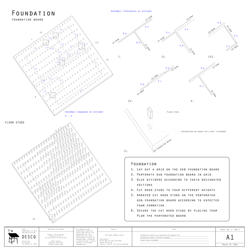
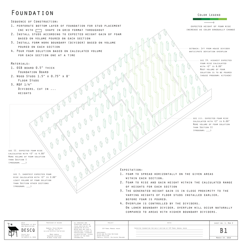
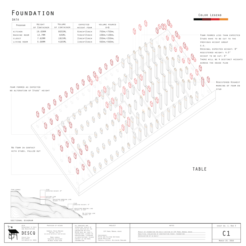
We created a construction manual for the house (Column A)., This manual introduces the assembly sequence of the parts but more than that it anticipates the form of the house. Based on the past experiments, we tried to control foam expansion by changing different variables such as type of foams, type of dividers, height of dividers, overflow of the foam, and order of pouring the foam solution. The idea is to find the controlled variable that will result in the greatest height gain and maximum overflow of the foam. We learned that materials behave under certain conditions. We derived a reasonable expectation of the foam expansion in the physical model. Expanding foam traditionally fills gaps, errors. In the SIP model, expanding foam fills up desired sections of cavity walls. The foam creates the gap, rather than closing the gap.
The first column of drawings are construction manual. It provides instructions on how to design and construct the house. The second column shows the house we anticipated. The third and the fourth column are the redline drawings. Redline drawings are conventionally used by contractors as a legal means to document the actual construction of the building that differs from the drawings given by the architects. In these drawings, they marked the deviations from the expectation in red lines. Furthermore, this project places a specific agency in the role of red lines to reinform the constructional sequence.
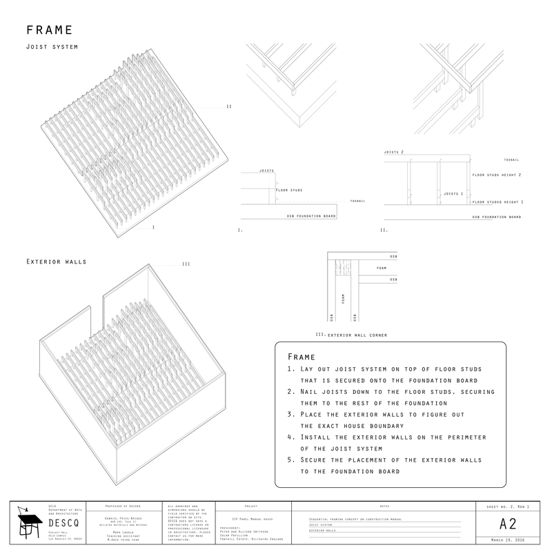
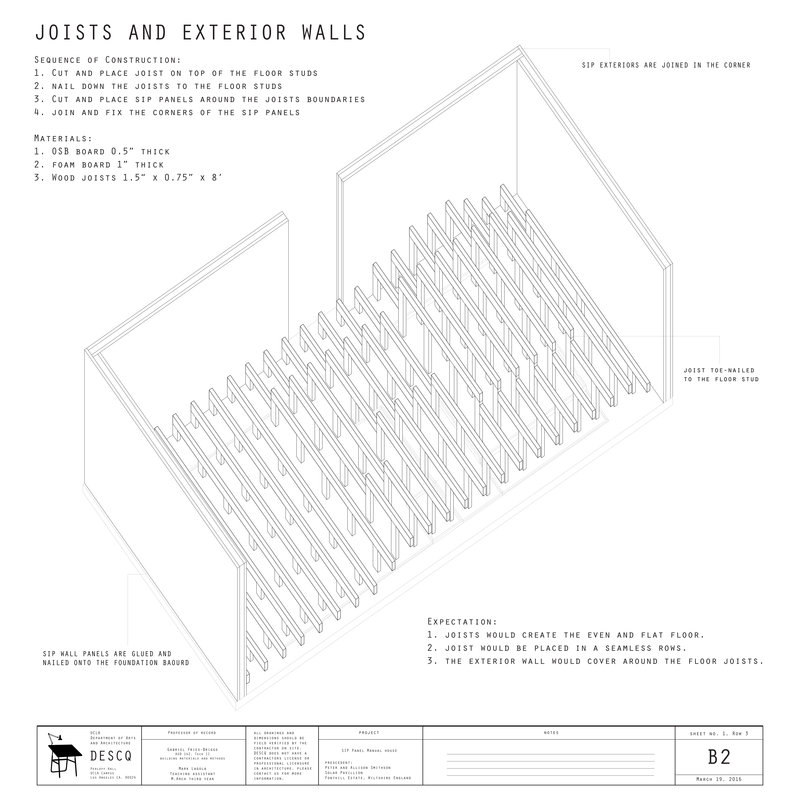
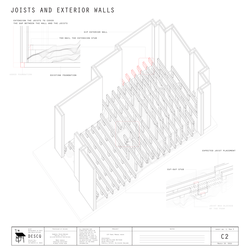
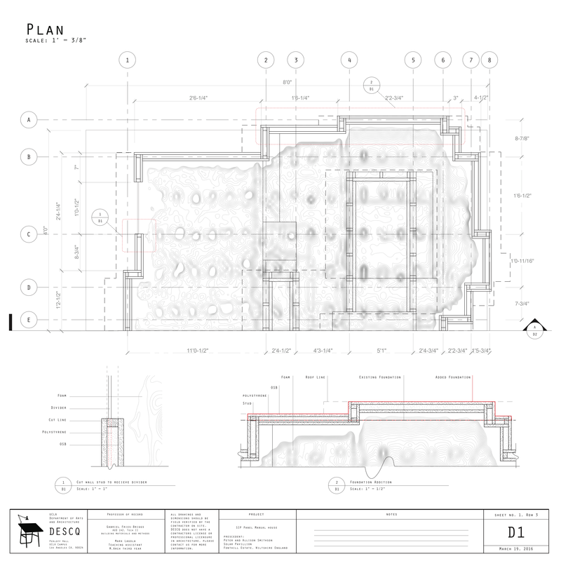
In A1 the manual describes the building sequence for the foundation, similarly, A2 describes the sequence for the flooring joists and exterior walls. In the B column each drawing corresponds to the manual as a prediction for how the building might look at each stage. The fabrication and assembly details are defined in these drawings. As you can see on A1 the cutting sequence is described, in B1 this cutting is simulated in the 3D prediction model. Similarly on A2 there are different details for the way the flooring joist system is constructed, and B2 shows how this system is implemented into the simulation model. The C column describes the actual built section of the Built Section of the SIP Panel Manual House. These drawings use the redlining technique that evelyn explained to describe tolerances and discrepancies between the actual and the expected model. The technique of redlining is used to inform the design of the next iteration of the building sequence. C1 describes the way that the studs were used to measure the foam as well as how they were cut based on the foam height to develop the floor heights.
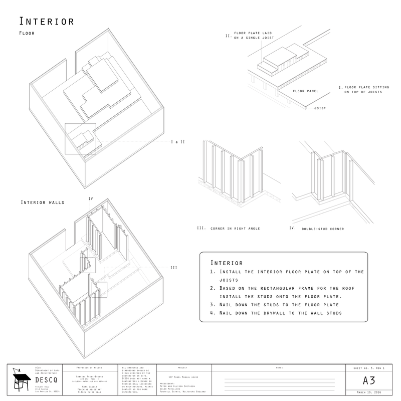
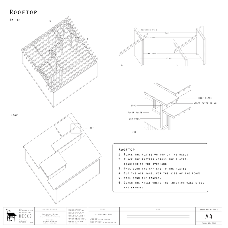
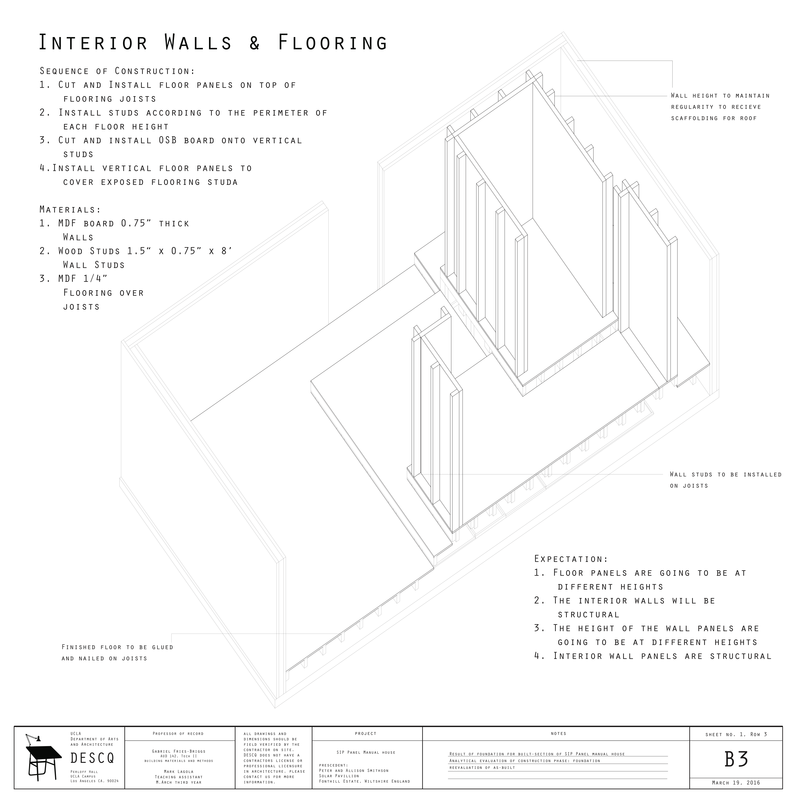
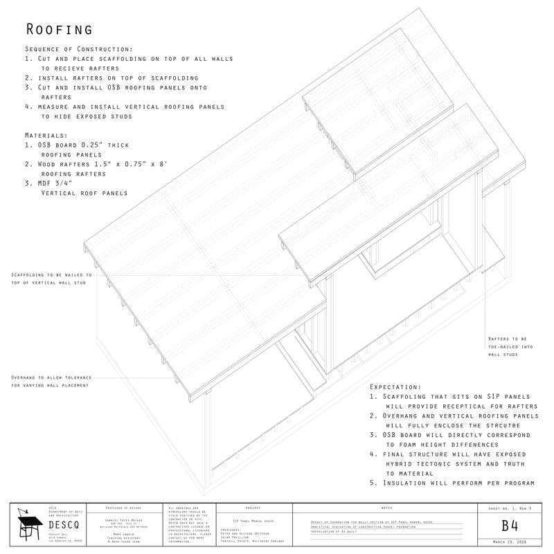
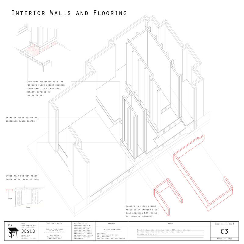
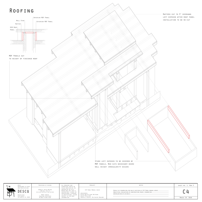
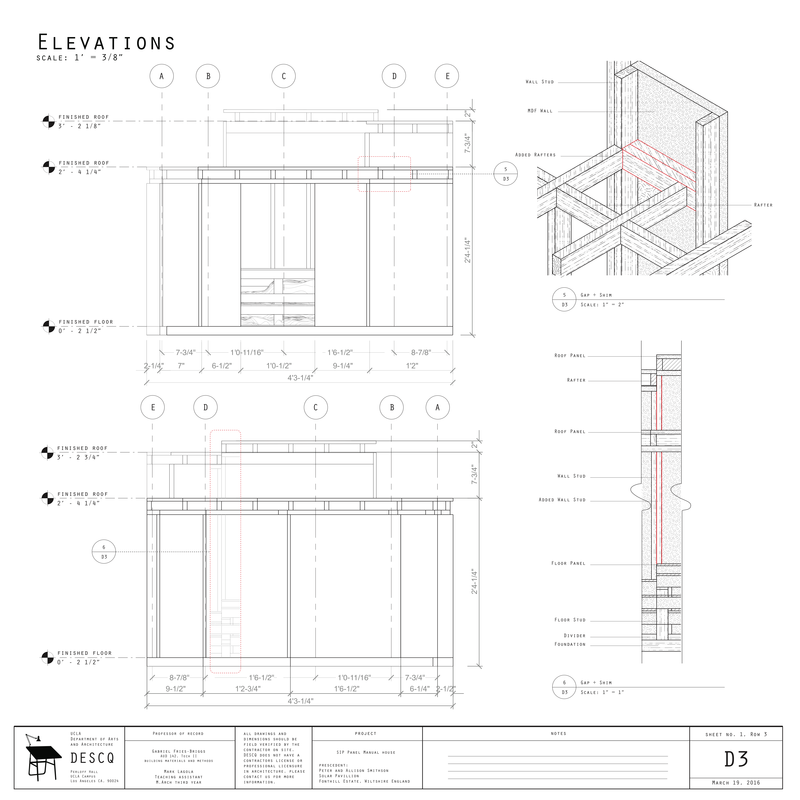
The drawings follow this same sequence throughout the building process where the asbuilt step in the sequence informs the design of the next iteration. For example in A3 the drawing shows the construction of the interior walls and floor plates. The details show how corners fit together under different conditions. This is then implemented into the simulation model as seen in B3. In C3 the actual model required extra vertical paneling on the floor plate to cover exposed studs that resulted from cutting the studs based on the expanding foam (as described in C1. The bottom column shows the same sequence for the roof which, in the actual model, necessitated a resolution between the different roof heights where studs were exposed, a tolerance which again can be attributed to the previous step in the sequence.
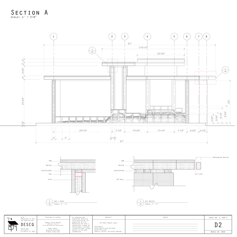
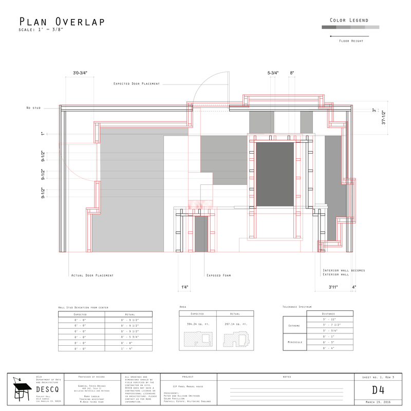
The complete plan, section and elevations of the actual sectional model of the actual built section of the Built Section of the SIP Panel Manual House are final construction documents based on our experiments. The details in each continue to use the red lining technique to describe tolerances and discrepancies between the expected and the actual. As you can see in D1, the irregular wall protruded past the existing foundation that was predicted to be sufficient in our predicted model. This necessitated the addition of new foundation to support the exterior wall and resulted from the feedback loop during reevaluation of the Exterior wall phase as seen in C2. In D2 you can see how short studs (point to first detail) and protruding rafters necessitated the addition of a shim and the subtraction of part of the roof (respectively). In D4 the plan of the expected is overlaid onto the actual plan. This is where discrepancies and tolerances between the predicted model and the actual one can be understood directly. The shaded parts show where floorplates overlapped at different heights and how the door location moved based on the expanding foam.
As is often the case in materialization, there was a gap between the expectation and the actual result. DESCQ measured the differences, documented them, and redesigned the following elements of the building. DESCQ repeated the process of designexperimentmeasuredocumentredesign. The “inaccurate” result is measured and documented. DESCQ redesigned the form to incorporate the inaccuracy into the built object. The inaccurate becomes the asbuilt through this feedback process.
This project presents new model of design & construction manual. Architects design the construction of built form, document the differences in red line, and redesign the form considering those differences. Design no longer precede construction. Instead, they feedback each other in a scientific process. Architects are scientists. Architects produce knowledge through papers and built form.
The first column of drawings are construction manual. It provides instructions on how to design and construct the house. The second column shows the house we anticipated. The third and the fourth column are the redline drawings. Redline drawings are conventionally used by contractors as a legal means to document the actual construction of the building that differs from the drawings given by the architects. In these drawings, they marked the deviations from the expectation in red lines. Furthermore, this project places a specific agency in the role of red lines to reinform the constructional sequence.
In A1 the manual describes the building sequence for the foundation, similarly, A2 describes the sequence for the flooring joists and exterior walls. In the B column each drawing corresponds to the manual as a prediction for how the building might look at each stage. The fabrication and assembly details are defined in these drawings. As you can see on A1 the cutting sequence is described, in B1 this cutting is simulated in the 3D prediction model. Similarly on A2 there are different details for the way the flooring joist system is constructed, and B2 shows how this system is implemented into the simulation model. The C column describes the actual built section of the Built Section of the SIP Panel Manual House. These drawings use the redlining technique that evelyn explained to describe tolerances and discrepancies between the actual and the expected model. The technique of redlining is used to inform the design of the next iteration of the building sequence. C1 describes the way that the studs were used to measure the foam as well as how they were cut based on the foam height to develop the floor heights.
The drawings follow this same sequence throughout the building process where the asbuilt step in the sequence informs the design of the next iteration. For example in A3 the drawing shows the construction of the interior walls and floor plates. The details show how corners fit together under different conditions. This is then implemented into the simulation model as seen in B3. In C3 the actual model required extra vertical paneling on the floor plate to cover exposed studs that resulted from cutting the studs based on the expanding foam (as described in C1. The bottom column shows the same sequence for the roof which, in the actual model, necessitated a resolution between the different roof heights where studs were exposed, a tolerance which again can be attributed to the previous step in the sequence.
The complete plan, section and elevations of the actual sectional model of the actual built section of the Built Section of the SIP Panel Manual House are final construction documents based on our experiments. The details in each continue to use the red lining technique to describe tolerances and discrepancies between the expected and the actual. As you can see in D1, the irregular wall protruded past the existing foundation that was predicted to be sufficient in our predicted model. This necessitated the addition of new foundation to support the exterior wall and resulted from the feedback loop during reevaluation of the Exterior wall phase as seen in C2. In D2 you can see how short studs (point to first detail) and protruding rafters necessitated the addition of a shim and the subtraction of part of the roof (respectively). In D4 the plan of the expected is overlaid onto the actual plan. This is where discrepancies and tolerances between the predicted model and the actual one can be understood directly. The shaded parts show where floorplates overlapped at different heights and how the door location moved based on the expanding foam.
As is often the case in materialization, there was a gap between the expectation and the actual result. DESCQ measured the differences, documented them, and redesigned the following elements of the building. DESCQ repeated the process of designexperimentmeasuredocumentredesign. The “inaccurate” result is measured and documented. DESCQ redesigned the form to incorporate the inaccuracy into the built object. The inaccurate becomes the asbuilt through this feedback process.
This project presents new model of design & construction manual. Architects design the construction of built form, document the differences in red line, and redesign the form considering those differences. Design no longer precede construction. Instead, they feedback each other in a scientific process. Architects are scientists. Architects produce knowledge through papers and built form.
